A windshield wiper is a device used to remove raindrops, snow, ice, and debris from a vehicle’s front window. Almost all motor vehicles, including cars, trucks, buses, train locomotives, and watercraft with a cabin—and some aircraft—are equipped with one or more such wipers, which are usually a legal requirement.
A wiper generally contains a metal arm. one end pivots and the other end has a long rubber blade attached to it. The arm is powered by a motor that is often an electric motor, anyway, pneumatic power is also used for some vehicles. The blade is wiping back and forth over the glass, pushing water, other precipitation, or any other impediments to visibility, from its surface. in vehicles that manufactured after 1969, the speed was normally adjustable, with several continuous speeds, and often one or more intermittent settings. Most personal automobiles use 2 synchronized radial-type wipers, while many commercial vehicles use one or more pantograph arms.
WIPER SPEED CONTROL
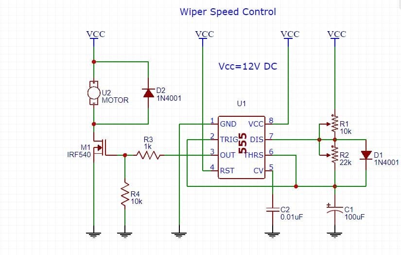
This project is about a simple car wiper speed controlling. The speed of the automobile wiper can be adjusted using a potentiometer using this circuit. This circuit operates in 12V DC and can be fitted to any automobile operating on 12V electrical system. With slight modification, the same circuit can be used to operate on 24V systems too.
555 TIMER IC
The 555 timer IC is an important part of electronics projects. Be it a simple project involving 8-bit micro-controller and such peripherals or a complex one involving system on chips, 555 timer working is involved. But these provide time delay, as an oscillator and also as a flip-flop element among in front of other applications. This 555 Introduced in 1971 by the American company Signetics, the 555 is still in use because of its low price, ease of use and stability. It is made by different companies in the original bipolar and low-power CMOS types in different periods. This is an estimate, a billion units were manufactured back in the single year 2003. Depending on the manufacturer, the standard 555 timer package includes 25 special transistors, 2 diodes also 15 resistors on a silicon chip installed in an 8-pin mini dual-in-line package Variants contain combining multiple chips on one board. However, 555 is still the most popular.
IRF540 MOSFET
The IRF540N is an N-Channel Mosfet. This MOSFET can drive loads up to 23A and can support peak current up to 110A. the Threshold voltage for this MOSFET is 4V, which means it can easily be driven by low voltages like 5V. Hence it is mostly used with Arduino and other microcontrollers for logic switching. This is not like transistors but transistors MOSFET’s are voltage-controlled devices. Meaning, they can be turned on or turned off by supplying the required Gate threshold voltage (VGS). IRF540N is an N-channel MOSFET, after that the Drain and Source pins can be left open when there is no voltage applied to the gate pin. When a gate voltage is applied after that these pin gets closed.
CIRCUIT DIAGRAM WORKING

The circuit is basically an astable multivibrator based on NE555 timer IC. IRF540 MOSFET is used for driving the wiper motor. IRF540 is an n-channel MOSFET with excellent characteristics. The maximum drain-source voltage is 100V, here maximum current in the drain is 22A and the drain-source resistance during switch-on is 0.055ohm.
The ON time of the astable multivibrator controls the sweep time of the wiper. It is governed by the equation Ton=0.69R1C1. The OFF time of the astable multivibrator controls the time between individual sweep cycles. It is governed by the equation Toff=0.69R2C1. Diode D1 by-passes resistor R2 during the charging of C1 and makes the ON time and OFF time independent of each other. Capacitor C2 is a noise by-pass capacitor. This capacitor prevents any noise from entering the chip through the control voltage(CV) pin.
When the output of main ic (NE555) is high (1), the MOSFET is switched ON and wiper motor is activated. When the output of the NE555 is low MOSFET is switched OFF and the wiper motor is held OFF. Resistor R3 limits the gate current of the MOSFET. Resistor R4 pulls down the gate of the MOSFET. Diode D2 is a freewheeling diode. It protects the switching device i.e. MOSFET from the voltage spikes produced when the motor is switched.
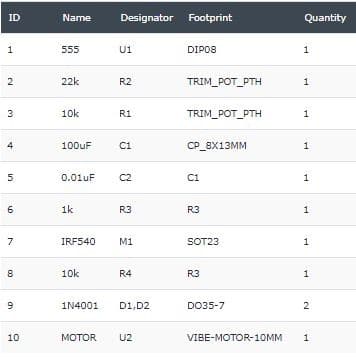
List of components

HOW TO SETUP THE CIRCUIT?
- You need some cuts in the wiring of your automobile to install this circuit.
- If your vehicle has two wiper motors, you can connect them in parallel.
- The total load current must not exceed 20A.
- Adjust preset R1 so that the wiper makes one sweep cycle.
- POT R2 can be used to vary sweep frequency (speed).
- R2 must be fitted on the dashboard where you have easy access.
If you have any queries feel free to connect us on social handles Facebook