Hello Reader, In this article, you will see how to make your own DIY induction heater easily with less number of components. Let’s get started…
Contents
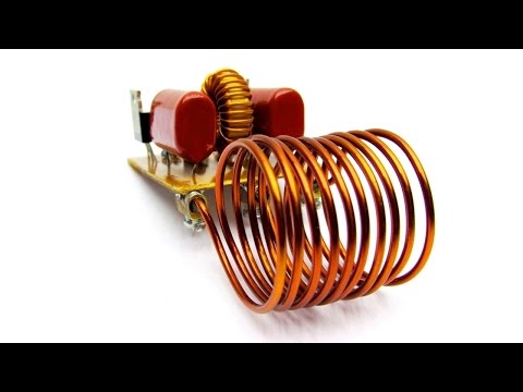
Induction Heater Circuit and Working

I used a simple push-pull oscillator circuit or the so-called ZVS driver.It is also often used in amateur structures
of induction heaters.The scheme (circuit) is so popular that there is lots of Chinese production.There are several variants of the scheme.We consider the case with the average point of the coil.
Alternate Working Induction Heater Circuit

In my opinion, it’s a bit more stable than two chokes without midpoint. In fact, it is a resonant converter, which
was built as an auto generator. Here each arm of the circuit must be treated as a separate oscillator.The optimum power supply voltage is 12V, although worked from 3.5V. The power supply should be sufficient to trigger the FETs.
I used the N- channel IRFZ44. Choke is taken from a computer ATX power supply.The core is made from iron powder.Gate resistors have two functions. They simultaneously limit the gate current and the current of Zener diodes.
The Zener prevents voltage increase through the gate and protects FET from breakdown.They maintain a stable operating voltage.Although experience shows that when powered from a stable source of 12V no need for Zener.The transformer primary winding is connected in parallel with a capacitor to form a resonant circuit.
By changing the parameters of these components the working frequency of the generator can be changed.As I have said before, the scheme often used for constructing simple induction heaters, although it is not an optimal due to the absence of the scheme for FETs regulation and good oscillator.
Large currents flow through the circuit, and the capacitor is also operated in hard conditions.Particularly, if the circuit is used as an induction heater, i.e. if the core is absent or it is not closed.Therefore, I advise you to use a battery of capacitors connected in parallel with a total capacity of 1 to 4.7 microfarads and voltage of 630 to 1600V. Optimally is 1000V. Practice shows that 400V, not enough.In the case of the capacitor bank, all should
have the same capacity and voltage. Simple, but the powerful high-voltage generator can be constructed on the basis of this driver and the TV flyback transformer.
At free part of the core do 2 * 5 or 2 * 6 turns of wire with a diameter of 0.8 mm. I advise using stranded copper wire with silicone insulation.If you use a flyback transformer from an old TV, be sure to fill additional resin on high-voltage winding.Otherwise, the transformer will burn.
Watch Video
If you have any queries feel free to connect us on social handles Facebook