Infrared light technology is the most commonly used wireless data transfer medium for a limited range. Today in this article, we will learn how to build a wonderful Wireless Audio Transfer Circuit from smartphone to speaker Using IR LEDs. Using this circuit you should be able to play songs from your iPod, mobile or computer to an external speaker without having to connect them directly through an AUX cable. The circuit comes with many limitations and there are better ways like Bluetooth to play songs wirelessly, hence this article only aims to help you understand simple audio circuits and at the same time have fun building it. Also, the circuit of this project is simplified as much as possible to keep things simple and reliable to make the build easier, so this should be a great weekend project to build and learn along with your friends. Now, that being said let’s get started!
Contents
Working Principle
The principle behind the circuit is that we will have two individual circuits. One is the transmitter circuit part and the other is the receiver circuit part, the transmitter circuit will be connected to the 3.5mm audio jack for audio input from the smartphone and the receiver circuit will be connected to a speaker to play the songs. The Audio signal will be transmitted through an IR LEDfrom the transmitter circuit; the IR signals will be then received by a photodiode which will be placed on the receiver circuit. The audio signal received by the photodiode is really weak and hence it can be amplified by an LM386 amplifier IC circuit and finally the output can get from a speaker.
It is very similar to your TV remote, when you press a button the IR led at the front of your TV, it transmits a signal which will be picked up by a photodiode (TSOP commonly) and the signal will be decoded to find which button you have pressed, check here the universal IR remote using TSOP. Similarly here the signal is transmitted will be an audio signal and the receiver will be a plain photodiode with a circuit that connected with a speaker. This technique will also work with normal LEDs and solar panels. This project is more related to Li-Fi technology
Components Required
- Breadboard (2)
- IR LED (2)
- 3.5mm Audio Jack
- LM386 IC
- Photo Diode
- 100K POT
- Resistors (1k, 10k, 100k)
- Capacitors (0.1uF, 10uF, 22uF)
IR based Audio Transmission System Circuit

Transmitter Circuit
The transmitter circuit only consists of a couple of IR LEDs and a resistor connected directly to the audio source and the battery. One tricky place where you might encounter a problem is with connecting the audio jack to the circuit. You must know that a normal Audio jack will have three output pins two for left and right earphone and the other is a shield which will be ground. We need one signal pin which can be either left or right and one ground pin for our circuit. You can use a multimeter in connectivity to find the right pinouts.
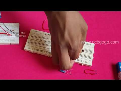
The working of the Transmitter circuit is pretty simple, the IR light from the IR LED acts as a carrier signal and the intensity of the IR light acts as a modulating signal. So if we power the IR led through an Audio source the battery will illuminate the IR led and the intensity with which it glows will be based on the audio signal. We have used two IR LEDs here just to increase the range of the circuit, otherwise, we can use even one. I build my circuit over a breadboard and the circuit can be powered anywhere between 5V to 9V, I used two 9V battery in place of the battery. The breadboard setup is shown below, I have connected my iPod here as an audio source but can use anything that has an Audio jack (Sorry iPhone users).
Receiver Circuit
Here a photodiode is connected to an Audio amplifier circuit. The Audio amplifier circuit is build using the popular LM386 IC, the advantage of this circuit is that its minimal requirement of components. This circuit can also be powered from a voltage ranging from 5V to 12V, I have used two 9Vbatteries in series.
Testing your Wireless Music Transfer Circuit
Once you connected both the circuits on the breadboard, give supply individually and connect the Audio source to the Transmitter part, first place the receiver circuit in line with the transmitter circuit within not more than 10cm and check if you hear the audio through the circuit. If not try adjusting the position of POT RV1 until you hear something. The complete working of the circuit can be found at the video linked at the bottom of this page.
Check this video for full connection and implementation
If you have any queries feel free to connect us on social handles Facebook