Introduction
In this tutorial, you will see how to connect i2c LCD display (Liquid Crystal Display) to Arduino using the i2c module. Before starting this article we will see what is i2c. I2C (I-square-C i.e IIC) means inter-integrated communication protocol. This is usually used to communicate between one master and multiple slaves. One of the best things about using I2C is we can reduce the connections (wiring). If you use normal LCD display, you need a total number of connections are 12. If you use I2C LCD display, you need only just 4 connection. By seeing the above example you may know the advantage of I2C protocol. I2C protocol is also known as 2 line protocol.
Contents
Components Required
Arduino Uno [ Amazon India / GearBest ]
I2C LCD Display/IIC LCD Display [ Amazon India / GearBest ]
Jumper Wires [ Amazon India / GearBest ]
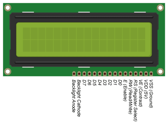
Pin Configuration of I2C LCD Display

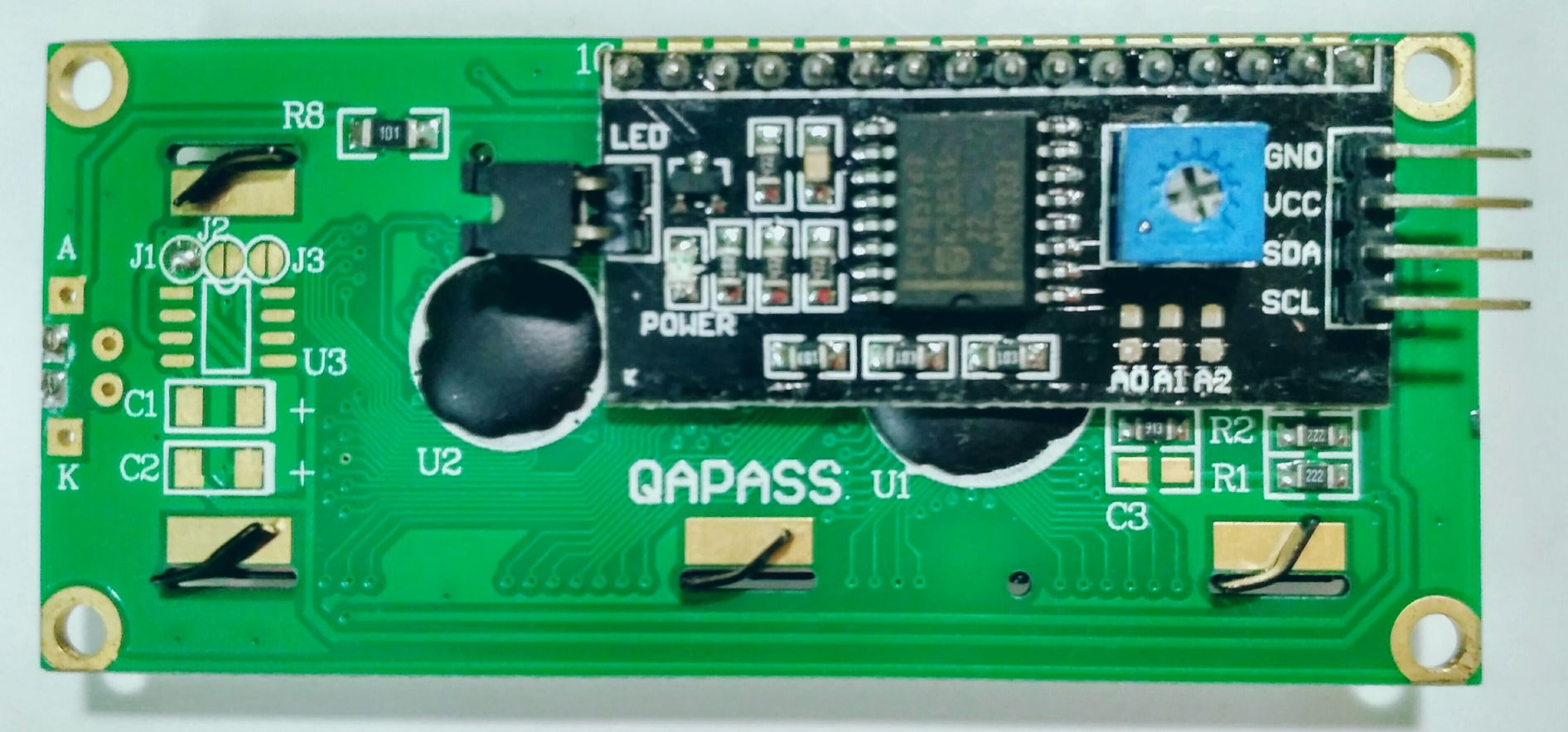
If you properly have seen the picture above, you will see a black adapter. That black adapter uses the PCF8574T IC chip which converts I2C serial data to parallel data for the LCD display. The blue color component you have seen in the above picture is a potentiometer which is used to adjust the brightness of the display.
Connections

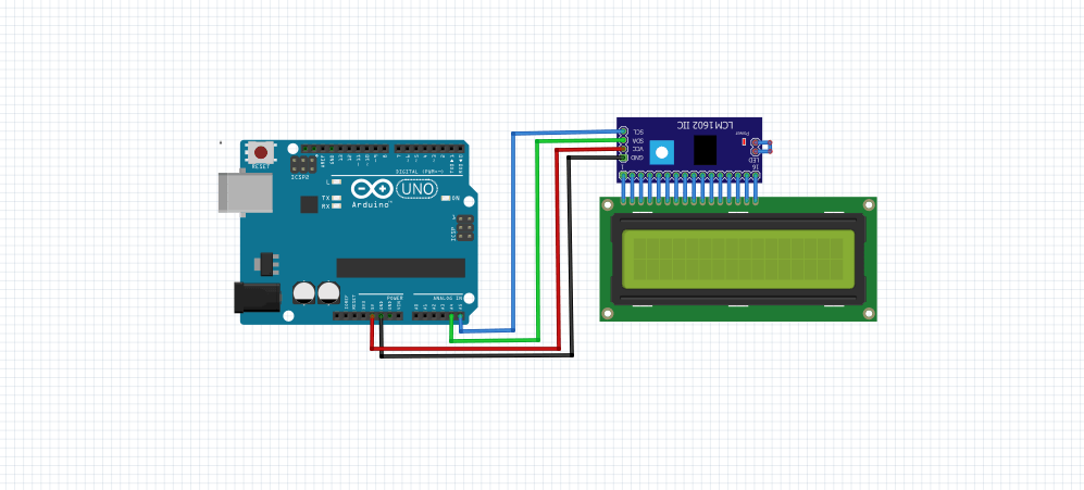
Arduino Uno <-> LCD Display
5V <—————> Vcc
GND <—————> GND
A4 <—————> SDA
A5 <—————> SCL
Source Code
/* www.electronicsprojectshub.com */
/*Import following Libraries*/
#include <Wire.h>
#include <LiquidCrystal_I2C.h>
//I2C pins declaration
LiquidCrystal_I2C lcd(0x27, 16, 2);

void setup()
{

lcd.begin();//Initializing display
lcd.backlight();//To Power ON the back light
//lcd.backlight();// To Power OFF the back light

}

void loop()
{
//Write your code
lcd.setCursor(0,0); //Defining positon to write from first row,first column .
lcd.print(" Tech Maker "); //You can write 16 Characters per line .
delay(1000);//Delay used to give a dynamic effect
lcd.setCursor(0,1);  //Defining positon to write from second row,first column .
lcd.print("Like | Share");
delay(8000);

lcd.clear();//Clean the screen
lcd.setCursor(0,0);
lcd.print(" SUBSCRIBE ");
lcd.setCursor(0,1);
lcd.print(" TECH MAKER ");
delay(8000);
}
Custom Characters
#include <Wire.h>
#include <LiquidCrystal_I2C.h>

uint8_t bell[8]  = {0x4, 0xe, 0xe, 0xe, 0x1f, 0x0, 0x4};
uint8_t note[8]  = {0x2, 0x3, 0x2, 0xe, 0x1e, 0xc, 0x0};
uint8_t clock[8] = {0x0, 0xe, 0x15, 0x17, 0x11, 0xe, 0x0};
uint8_t heart[8] = {0x0, 0xa, 0x1f, 0x1f, 0xe, 0x4, 0x0};
uint8_t duck[8]  = {0x0, 0xc, 0x1d, 0xf, 0xf, 0x6, 0x0};
uint8_t check[8] = {0x0, 0x1 ,0x3, 0x16, 0x1c, 0x8, 0x0};
uint8_t cross[8] = {0x0, 0x1b, 0xe, 0x4, 0xe, 0x1b, 0x0};
uint8_t retarrow[8] = {	0x1, 0x1, 0x5, 0x9, 0x1f, 0x8, 0x4};

// Set the LCD address to 0x27 for a 16 chars and 2 line display
LiquidCrystal_I2C lcd(0x27, 16, 2);

void setup()
{
  lcd.begin();
  lcd.backlight();

  lcd.createChar(0, bell);
  lcd.createChar(1, note);
  lcd.createChar(2, clock);
  lcd.createChar(3, heart);
  lcd.createChar(4, duck);
  lcd.createChar(5, check);
  lcd.createChar(6, cross);
  lcd.createChar(7, retarrow);
  lcd.home();

  lcd.print("Hello world...");
  lcd.setCursor(0, 1);
  lcd.print(" i ");
  lcd.write(3);
  lcd.print(" arduinos!");
  delay(5000);
  displayKeyCodes();
}

// display all keycodes
void displayKeyCodes(void) {
  uint8_t i = 0;

  while (1) {
    lcd.clear();
    lcd.print("Codes 0x");
    lcd.print(i, HEX);
    lcd.print("-0x");
    lcd.print(i + 16, HEX);
    lcd.setCursor(0, 1);

    for (int j = 0; j < 16; j++) {
      lcd.write(i + j);
    }
    i += 16;

    delay(4000);
  }
}

void loop()
{
  // Do nothing here...
}Display Text sent over Serial Port in LCD Display
#include <Wire.h>
#include <LiquidCrystal_I2C.h>

// Set the LCD address to 0x27 for a 16 chars and 2 line display
LiquidCrystal_I2C lcd(0x27, 16, 2);

void setup()
{
  lcd.begin();
  lcd.backlight();

  // Initialize the serial port at a speed of 9600 baud
  Serial.begin(9600);
}

void loop()
{
  // If characters arrived over the serial port...
  if (Serial.available()) {
    // Wait a bit for the entire message to arrive
    delay(100);
    // Clear the screen
    lcd.clear();

    // Write all characters received with the serial port to the LCD.
    while (Serial.available() > 0) {
      lcd.write(Serial.read());
    }
  }
}Download I2C LCD Arduino Code and Library
Procedure
- Download and Install the Library attached.
- Download the code.
- Connect the components as the circuit attached.
- Edit the code as need to change the text on LCD.
- Upload the downloaded code.
- Now you can see the text on LCD.
Watch Video
Working of LCD Display
The LCD display has an inbuilt register, to store the data and commands given to the LCD display. It has two modes, one is READ mode and another is WRITE mode. In write mode commands to control the display is written to the register like display clear, shift right, the cursor on, etc., In WRITE mode the register is also written with data which is needed to be displayed on the display. Here a question arises how to differentiate between commands and data written to the register. There a pin called Register select (RS), if that pin is made to zero, then it is command register. If it is one, then it is a data register.
The selection of READ / WRITE is done by a pin R/W. If R/W is equal to zero, then it is write mode. If R/W is equal to one it is read mode.

click on the link for more projects and tutorials on Arduino.
If you have any queries feel free to connect us on social handles Facebook