If you are looking for a first-class forty-watt music stereo amplifier, then look no further. Build this and turn on the volume and watch your neighbors live up to its name!
Contents
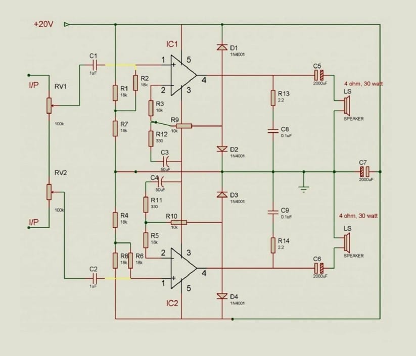
High output efficiency, negligible hum, low harmonic distortion, clarity of the output sound, compact (modular) size, and low cost are some of the key features of this fully solid-state integrated Hi-Fi stereo amplifier which is capable of delivering an output of over twenty watts into each channel. The circuit uses a minimum of components and is built around just two power ICs. Upon adding just a simple preamplifier, the circuit can be converted into a forty-watt stereo cassette player.
Components Required
- Semiconductors
- IC1,IC2 LM1875
- D1-D4 1N4001 diodes
- Resistors (all 1/2 watt, 5%)
- R1-R8 18k
- R9,R10 10k
- RV1,RV2 100k with plastic shaft
- R13,R14 2.2 ohms, 2 pieces for Zobel network
- Capacitors
- C1,C2 1uF (non-polar)
- C3,C4 50uF (electrolytic)
- C5,C6,C7 2mF or 2000uF
- C8,C9 0.1uF ceramic
- Miscellaneous
- LS 4 ohms, 30 watts loudspeakers with cabinet, 2 pieces
- PCB
- Knobs
- Speaker cables
2 Channel Hifi Stereo Amplifier Circuit

Working
The circuit is based on an LM1875 monolithic amplifier chip from National Semiconductors. The amplifier works in a way more or less similar to an op-amp. The 1 uF non-polar capacitors provide input coupling and the 2200 uF capacitors provide output coupling. The potentiometers RV1 and RV2 provide volume control.
The power supply consists of a conventional full-wave rectifier and filter. The LED provides an operating indication. Read working of the operational amplifier to understand how an audio signal is amplified
An array of psychedelic LEDs can also be added. Similarly, tone controls can also be introduced before volume controls.
Construction
The circuit can be constructed on a PCB. The ICs should be bolted to the PCB and heat sink before they are soldered. The soldering should be done using 40/60 type core. First, the resistors, then capacitors, and lastly the semiconductors should be soldered to the PCB. A 25-watt rod should be used for this purpose. The extra lead lengths should be cut off only after soldering is complete. The PCB should be cleaned with petrol and copper side painted over to prevent oxidation. The controls should be connected using shielded wires. Now recheck the entire wiring and if all is correct, switch on the unit, turn on the volume and watch your neighbors live up to its name!
Below circuits are to make power supply and psychedelic LEDs, make if you don’t have.
Power Supply Unit
Components required
- Semiconductors
- D1,D2 1N5408 diode
- D3 LED
- Resistors
- R1 1.5k (1/2 watt)
- Capacitors
- C1 2000uF (50v electrolytic)
- Miscellaneous
- X1 15 volts, 3.4 ampere transformer
- PCB
- Cables
Power Supply Circuit
Psychedelic LEDs
Components Required
- Semiconductors
- Q1,Q2 SL100 NPN Transistor
- D1-D6 Red LEDs
- D7,D8 1N4148
- Resistors
- R1,R2 820 ohms
- Miscellaneous
- PCB
- Hook up cables
Psychedelic LEDs Circuit
Authored By: Abhishek Singh (hackatronic.com)