In this article, you will learn how to make an programmable electronic dice easily in breadboard with less number of components.
Contents
Lets gets Started …
Components Required
- Breadboard
- Common Anode 7 segment display
- IC7413
- IC74191
- IC7447
- 4 way DIP switch
- Resistors
Programmable Electronic Dice Circuit
Programmable Electronic Dice Circuit Working
IC7413
IC 7413 is a dual 4−Input NAND Schmitt trigger in a 14−Lead plastic DIP-type package. The device is temperature−compensated and can be triggered from the slowest of input ramps and still give clean, jitter-free output signals.
IC74191
IC74191 is a Synchronous 4-Bit Up/Down Counter with Mode Control. Synchronous operation is provided by having all flip-flops clocked simultaneously so that the outputs change simultaneously when so instructed by the steering logic. This mode of operation eliminates the output counting spikes normally associated with asynchronous (ripple clock) counters. The outputs of the four master-slave flip-flops are triggered on a LOW-to-HIGH level transition of the clock input if the enable input is LOW. A HIGH at the enable input inhibits counting. Level changes at either the enable input or the down/up input should be made only when the clock input is HIGH. The direction of the count is determined by the level of the down/up input. When LOW, the counter counts up and when HIGH, it counts down. The counter is fully programmable; that is, the outputs may be preset to either level by placing a LOW on the load input and entering the desired data at the data inputs. The output will change independent of the level of the clock input. This feature allows the counters to be used as modulo-N dividers by simply modifying the count length with the preset inputs.
IC7447
74LS47 is a BCD to 7-segment decoder/driver IC. It accepts a binary coded decimal as input and converts it into a pattern to drive a seven-segment for displaying digits 0 to 9. Binary coded decimal (BCD) is an encoding in which each digit of a number is represented by its own binary sequence (usually of four bits).
For example 239 in BCD is represented as 0010 0011 1001.
74LS47 IC accepts four lines of BCD (8421) input data and generates their complements internally. The data is decoded with seven AND/OR gates to drive indicator LEDs of the seven segment directly. The outputs correspond to Common anode (CA) configuration of seven segments.
Working
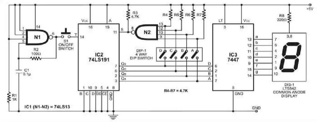
IC1 is a dual 4-input Schmitt trigger NAND gate 74LS13. Gate N1 is used as an oscillator built using resistor R2 and capacitor C1 to produce approximately 70kHz clock frequency, which is fed to IC2. Gate N2 loads data at the inputs of IC2.
IC2 is a presettable binary counter (74LS191) with parallel loading facility. Whenever its pin 11 goes low, the data present at its inputs D through A (which is ‘0001’) appears at its outputs QD through QA when all the inner switches of DIP switch are open and DIS1 shows the minimum count as ‘1’ (and not ‘0’).
Circuit Operation
To obtain the desired dice range, inner switches A, B, C and D of DIP switch are to be set as per the table. For example, if you want the electronic dice to count from 1 to 8, close switches A and D and keep B and C open. On pressing switch S1, the display varies fast between ‘1’ and ‘8.’ When you release S1, the display stops shuffling and the last (latest) number remains on it.
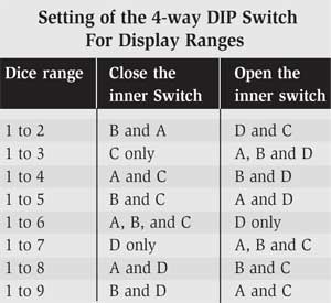
With inner switches of DIP switch in positions shown in the table, the count output can go from ‘0001’ to the maximum count shown under ‘Dice Range’ in the table when switch S1 is depressed. On releasing switch S1, the last count within the dice range gets displayed.
The outputs of IC2 are displayed on common-anode, 7-segment display LTS542 (DIS1). BCD-to-7-segment decoder IC 7447 (IC3) is used to drive the display. Resistor R8 limits the current through DIS1.
If you have any queries feel free to connect us on social handles Facebook